Model Description
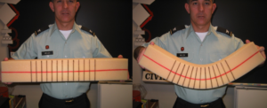
This simple demonstration depicts how moments (and forces) result in bending of a beam and how the deformation is related to the assumptions associated with elastic beam behavior. A foam beam with vertical lines (black lines) and a horizontal line drawn along the neutral axis (red line) for a rectangular beam is used to demonstrate bending behavior. The orientation of the lines during bending provides a simple physical representation of flexural theory (figure below, left). This demonstration should take 3-5 minutes.

Engineering Principle
The foam beam can be used to show many concepts surrounding flexural behavior, but the easiest and possibly most difficult to visualize without a physical model is plane sections remain plane. Additionally, many students will be able to see that a positive moment (based on the established sign convention) results in the beam that looks like a smile in which the top fibers are in compression and the bottom fibers are in tension while the fibers at some point in between are not experiencing tension or compression, i.e., the neutral axis (figure above, right).
What You Need
| Item | Quantity | Description/Clarification |
|---|---|---|
| Foam Beam | 1 | The beam can be any reasonable size. This example used a 23.5 inch long beam with a 4″x4″ square cross-section in the first two images. A 2”x2”x12” foam beam works just as well. The material is basic furniture foam. |
| Markers | 2 colors |
These are used to draw lines on the beam. One color (red) is used for a horizontal line down the whole length of the beam in the middle (neutral surface). Ten to fifteen vertical lines are drawn towards the middle of the beam, spaced about an inch apart, with the other color (black). |
How It’s Done
Before Class: Prepare the beam with the lines drawn on it.
In Class: Show the class the beam (figure below, left) and ask what they think will happen when you apply a moment to it. More directed questions could be: Which lines will change shape and/or orientation? What will happen to the distance between the black lines?
Then apply a moment using a hand at each end of the beam so that the beam begins to bend into a slight smile and ask what just happened (figure below, right). Point out the deformation of the red line—it is now curved—but that it did not change in length while the top surface and the bottom surface did change length. This can be seen by observing the change in the space between the black lines. At the top of the beam, the lines moved closer together (compression), while at the bottom of the beam the lines moved farther apart (tension). The distance between black lines along the red line is still the same. But also point out that the black lines themselves did not deform – they are still straight. Plane sections remain plane during elastic bending. The change in the spacing of the lines shows that the top of the beam is in compression, and the bottom is in tension.
Note: The size of the rectangular beams does not matter. A 2 inch square foam beam can also be used.

Additional Application: There is usually a lot of confusion as to when the assumptions of flexural behavior are no longer valid. The foam beam can be used to provide some insight into the fact that flexural theory is only valid when the assumptions are valid. Bending a beam to the point that the vertical lines are no longer straight visually demonstrates that the assumptions are no longer valid when the beam experiences large deflections and plane sections are no longer plane. The students can see this theory under the large deformations the beam is experiencing and the professor can further enforce that the assumptions (and associated flexural equations) are only valid for elastic conditions (figure below, left).
When discussing torsion, torsional loads on square shapes causes warping and is very difficult to determine how much of the material is resisting the applied twisting moments (figure below, right).

