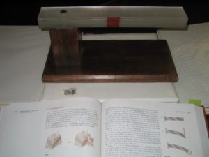
Model Description
These demonstrations show the effects of shear within rectangular members. This demonstration should take 10-15 minutes.
Engineering Principle
When a load perpendicular to the longitudinal axis is applied to a beam, the force is transferred through the beam through shear. With the help of these two demonstrations, the students will better understand how a load applied perpendicular to the longitudinal axis is transferred to the reactions of the beam. The goal is to demonstrate how the force is transferred through horizontal shear and to establish a physical representation to the development of the theory on shear in rectangular beams. Additionally, these physical models highlight how members fail if caused by shear.
What You Need
| Item | Quantity | Description/Clarification |
|---|---|---|
| Plastic Rectangles | 12 | These are clear pieces of plastic 12″ long x 2″ wide x ⅛” thick. Eight of them are stacked on each other and connected at one end by a screw driven through them into a piece of wood. The other four are used for the other prop. These have three holes in them: two oblong holes about 3″ from each end, 1″ long and ½” wide, and a third hole in the middle of the member, ½” diameter. |
| Red Marker | 1 | This is used to draw a square on the member made of the 8 plastic rectangles. The rectangle is right in the middle of the member and drawn on the edge of the members. |
| Nut and Bolt | 1 | 5½” bolt with a matching nut to attach the two pieces of wood to the plastic. |
| Base | 1 | The base is made of two pieces of wood—the top piece 3¾” x 2½” x 2½” and the bottom piece 12” x 6” x ¾”. The two are connected with a screw and a nut so that the top piece is on one edge of the bottom piece to establish the condition that the connection of the plastic pieces results in a cantilever beam. |
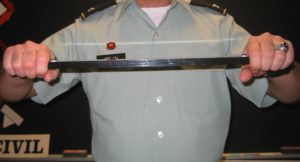
| Yardstick | 1 | The ruler is used as a sort of introduction to shear. Applying a load to it brings around the question of how a load applied to the middle of a beam gets to the ends of the beam. |
How It’s Done
Before Class: Prepare the two props and test them to be sure that you can create the proper effect.
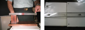
In Class: Take the ruler and have two people hold each end. Apply a small load to the middle to make the ruler bend (figure below, left). Ask the two students if they felt a force on the ends of the ruler. When an affirmative answer is given, challenge the class by asking how they think the vertical load got from the middle of the beam to the ends. After a bit of discussion, bring out the first demonstration.
Show the students the demonstrator with the plastic strips attached to the base (cantilever). Ask what they think will happen to the beam and the square in the middle when you apply a force to the free side of the cantilevered beam. Press down on the beam and show how the square deforms (as the pieces of plastic slide) (figure above, right). Relate this to the shape of the square on the side of a cylindrical rod.
Ask the class: what is happening to the fibers inside of a solid beam (one not made up of eight strips of plastic strips). Explain how the forces are working in the beam. There is a force applied downwards on the free side of the beam, and therefore a force acting upwards on the other side to put the beam in equilibrium. Ask then how these forces would tend to make the square move if they were the only forces in the beam. Show how the square would rotate with these forces.

What forces keep this rotation from occurring? There must be horizontal forces equal to the vertical forces that keep the square from rotating. These forces cause the square to deform into a rhombus shape.

Why is shear so important? Shear is the least understood phenomenon. If overlooked, shear forces can cause failure, and they often do. The second demonstration shows why. Hold the four lengths of plastic attached at both ends and once again ask the class what they think will happen if you apply a moment to bend the member.
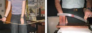
Bend the member and point out the sliding of the sections of the member, how they don’t line up at the ends any more and how they separate in the middle when the force is slowly relieved (figure below, left). This is how member will fail at the end of a member (ends of a simply supported beam) when they are acted upon by the resulting internal shear forces caused by a load applied perpendicular to the longitudinal axis (figure below, right). This is also how a vertical load is transferred horizontally along the length of the beam to the usual vertical reaction at the end points, especially in a simply supported beam.

Additional Application: Ask the class if they can think of an example of a material that acts like these sectioned members. Ask if anyone has seen an old wooden bridge that has begun to split at the ends and talk about how wood reacts to shear forces. Because of a wood’s grain, it is very strong if forces are applied perpendicular to the grain. But when forces, like shear, are applied along (horizontally) the grain, the wood begins to fail because it splits much more easily along the grain than against the grain.
