Model Description
Use this daunting looking model to set the stage for a lesson on 3-D equilibrium and eventually persuade your students that it’s easier than it looks! This demonstration should take 20 minutes.
Engineering Principle
3-D equilibrium for a non-concurrent force system requires the simultaneous solution of six equations of equilibrium, three equations for summing forces and three equations for summing moments about each axis.
In order to keep all of these equations and forces organized, it becomes important to begin to describe forces and moments with Cartesian vectors and to use matrix algebra to solve the systems of equations that result from application of the principle of equilibrium. For Example, the Moment and Force Reactions at a fixed support might be described as:
Some supports will not hinder translation in or rotation about one or more axis. In this case, the value for the magnitude given by A-F above will be zero. In order to describe a force as a vector given the force’s magnitude and line of action, one must first determine the unit vector of the force, then multiply it by the force’s magnitude. For example, the Unit vector describing a force with a line of action from point A to point B is found by dividing the position vector from A to B by the magnitude of that vector.
Once the unit vector is found, the Force vector can be calculated by multiplying the unit vector by the force magnitude, which is f in this case.
The final key element to determining equilibrium in 3D is to determine the Moment vector that is caused by any force vector acting at a distance from a point. In order to determine this, the cross product is used between the position vector from the point in question to any point along the force’s line of action and the Force vector. Using our previous example, the Moment caused by our Force AB about point 0 would be given by the cross product of a position vector from point 0 to any point along the force’s line of action (in this case we chose point A) and the Force vector AB.
Armed with these basics, 3D equilibrium problems can be easily solved.
What You Need
| Item | Quantity | Description/Clarification |
|---|---|---|
| Force Vector | 2 |
Each Vector represents one force acting on the PVC pipe system. Construct out of cardboard or foam. |
| Moment Vector | 1 |
This vector represents a moment acting on the PVC pipe system. Construct out of cardboard or foam. |
|
¾ “ PVC Pipe |
75 cm |
The scale of this model is 1:10. The pipe should be cut into 3 pieces of 20cm, 25cm, and 30cm. |
|
¾” 90° PVC Pipe elbow |
2 |
|
|
¾” threaded PVC Pipe end |
1 |
|
|
Threaded Pipe Mount |
1 |
This section mounts to the 2”x 4” base with screws and holds the threaded PVC pipe end. |
|
2” x 4” |
25 cm |
This is the base of the persuader that can be mounted to a wall or door with a few clamps. |
|
2” Nail |
3 |
These nails will hold the force and moment vectors to the model. |
|
¾” Screw |
4 |
These screws mount the pipe mount to the 2”x 4” base piece. |
How It’s Done
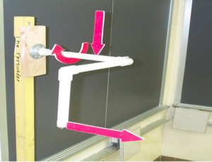
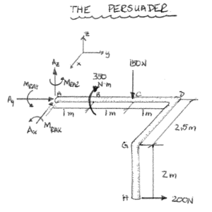
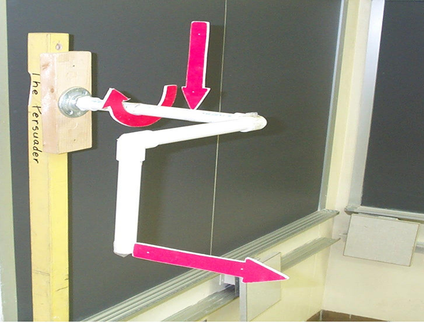
Before Class: Build the Demonstrator (Fig. 1). Refer to the Free Body Diagram (Fig. 2) for assistance when building the demonstrator. Mount the threaded pipe mount to the center of the 2”x 4” section. Thread the PVC pipe end piece into the pipe mount. Connect the 30 cm section of pipe to the threaded end piece. Place a 90° elbow on the opposite end of the 30 cm section. Connect the 25 cm section of pipe to the 90° elbow. Place another 90° elbow on the opposite end of the 25 cm section. The final 20 cm pipe section should then connect to the elbow. Drill holes through the pipe at the locations for each of the externally applied forces and moments. These holes should be large enough to pass one of the 2” nails through. The nails should be glued down and hold the force and moment vectors to the apparatus. One additional step that can be helpful is to label the points and distances on the Persuader with either permanent marker or by taping small pieces of paper to it.

Fig. 1

Fig. 2
In Class:
At the beginning of class, point out the persuader and really build it up as a very difficult problem to solve, but that by the end of class it will be one that they can solve with ease. Begin by defining a Cartesian vector in 3 dimensions and what it means. Then, discuss support conditions in 3 dimensions and what vector support reactions would result from a fixed, hinge, cable, and other types of supports. Next, review how to describe a force with a certain line of action and magnitude by a Cartesian vector. First, determine the position vector for the line of action, then calculate the unit vector by dividing the position vector by its’ magnitude. Finally, multiply the magnitude of the force by the unit vector to get the Cartesian force vector. The final step prior to being able to solve “the Persuader” is to review the procedure for calculating the moment of a force about a point in 3D space by using the cross product.
Translate the Persuader into a free body diagram on the board by isolating the body and replacing the support with the respective reactions that would occur. The free body diagram should look like Fig. 2 shown above when completed.
Once that is complete, the process of writing all of the force vectors and position vectors, then applying the equations of equilibrium is really quite painless. Show the students how to organize their equations into a table or a matrix in order to keep all of the unknowns straight in the equations.

