Model Description
This is an opportunity to hang something from the ceiling and excite the students about their ability to analyze real world structures. After a few weeks of statics lessons, students possess the ability to determine the maximum and minimum force in a cable suspension bridge through equations of equilibrium. This demonstration should take 30 minutes.
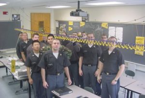
Fig. 1
Engineering Principle
This physical model provides a visual aid to illustrate the main components of a uniformly loaded cable, or more specifically, a cable suspension bridge. This can be supplemented with a simple board problem that demonstrates distributed loads and how “droop” in the cable from tower to center span can be modeled with simple statics. This statics exercise can be used to demonstrate that the compression in the tower remains constant but the tension in the cable goes down as the towers get taller, which provides a great opportunity to talk about the relationship between statics, design, and cost.
What You Need
| Item | Quantity | Description/Clarification |
|---|---|---|
| Rope or Cord | 60 to 80 ft | This is the main cable and varies depending on the size you want to construct |
| KNEX Truss Deck | 1 | Size dependent – construction tips below |
| String | 1 roll |
Connects the cables and deck (hangers) |
| Binder or Alligator Clips | 2 per string |
Clip strings to cables – quick and easy |
How It’s Done
Before Class:
This can be built once and stored for the following semester. As pictured, seven 3ft sections are utilized but this can vary depending on the size of the classroom and how many KNEX and how much patience the instructor has. Short white connecter pieces allow the sections to quickly connect to each other. Each 3 foot section as pictured below consists of the following KNEX pieces: 87 ea Blue; 52 ea Purple Connectors (compression); 24 ea Yellow 26 ea Yellow Connectors (tension); 4 ea White
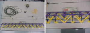
Fig. 2
Run the cord (that’s the main cable) though some eyelets or hooks in the ceiling and tie off the ends. Stack a couple desks (temporary shoring) on each other to get the deck near its final position. Run the string (that’s the hangers connecting the main cable and the deck) through the deck and clip to the main cables (cords). Some raising and adjustment will be necessary – but the student reaction makes it well worth it.
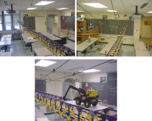
Fig. 3
In Class: Discuss the main components of the bridge; main cable, “hanger” cables, stiffening truss and running surface. Use this physical model to really drive home to your students that they have already learned to do something significant in terms of design. During class, it helps to solve for the tension in the main cable and the reactions at the towers. Talk about how varying the tower height effects the forces involved, thereby impacting the cost and aesthetics of the bridge. Also, discuss how a roller at the top of the tower ensures only compressive forces on the tower.
Additional Application:
We use this lesson to derive the formula for the maximum tension in the cable through use of a good free body diagram and equations of equilibrium. After this, we watch the Discovery Channel special “Engineering the Impossible: Bridge over the Gibraltar Straight.” This 30 minute segment is outstanding. A smaller suspension bridge, an actual wire cable bundle, and FBD are pictured below.
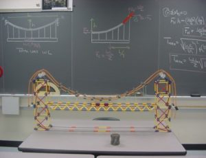
Fig. 4
Don’t have a ceiling to hang the cable from? No problem – use the students! We have also utilized the same physical model to talk through the different stages of engineering design and construction. Cool!
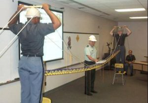
Fig. 5
