Model Description
This is a simple demonstration to introduce the basic principles of truss behavior and analysis. It will show how the shape of a truss—and not necessarily its weight/material—determines its stability. A simple truss design will be used to show that triangles are the important stability shape used in trusses rather than squares or rectangles. This demonstration should take 15-20 minutes.
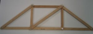
Fig. 1
Engineering Principle
The basic equations required for analysis are the equations of equilibrium and trigonometry. However, no real numerical analysis is required. The model is used primarily for developing a feel for the basic definition for a truss: a structure composed of slender members joined together at end points by frictionless pins; loads only applied at joints; all truss members are 2-force members; and member weight is negligible.
What You Need
| Item | Quantity | Description/Clarification |
|---|---|---|
| Pieces of Wood | 9 | Any wood type can be used to include scrap pieces from a previous project! In the picture provided, each piece is an inch wide and about a quarter of an inch thick. Each piece needs one hole drilled in each end so that they all can be connected with nuts and bolts. Pieced together, they make a truss with 4 triangles, with the two middle triangles able to be combined into a square by removing the diagonal member. 4 pieces (members) need holes 12 inches apart. 3 pieces (members) need holes 15 inches apart. 2 pieces (members) need holes 9 inches apart. Holes are slightly larger than 3/8 inch for this example. |
| Bolts | 6 | 4 bolts need to be 1.5 inches long x 3/8 inch and the other two can be 1 inch long x 3/8 inch. Diameters other that 3/8 inch can be used – just ensure the holes and bolt diameters match. |
| Nuts | 6 | Nut diameter to match the bolts. The 6 bolts connect 8 of the 9 members in place, but are screwed finger tight so that they all can move relatively freely (pinned connection). The middle diagonal member is just placed on the ends of the longer bolts after the nuts are screwed on for easy removal. |
How It’s Done
Before Class: Construct the truss out of the eight members and six nuts/bolts. Be certain that the joints are finger tight to move freely when the diagonal member is not in place.
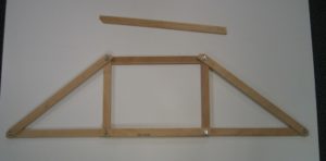
Fig. 2
In Class: Through questioning of the students define a truss: a figure consisting of straight, slender members connected at joints by frictionless pins. Show the class the truss without the center diagonal member and give it to two students to hold between two desks so that it doesn’t look unstable (Fig. 3, left). Have a third student apply force to one of the top two joints, making the figure easily fail (Fig. 3, right)
Ask the students what they think the problem is with the truss. Try tightening the bolts even further with your fingers to see if that is the problem. Once the correct answer is given – the truss members must form triangular shapes when connected, correct the truss by placing the diagonal member on the bolts (so that is what this extra member is for…!).
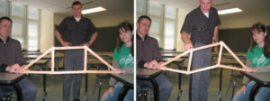
Fig. 3
Demonstrate how much stronger this design is by having the same student push on each of the top joints while the other two are holding it (Fig. 4, left). Ask the student to describe quantitatively how much stronger/stable the truss is with the diagonal member in place (Fig. 4, right).
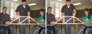
Fig. 4
Additional Application:
A discussion can now ensue concerning each of the portions/assumptions of the definition of a truss: a structure composed of slender members joined together at end points by frictionless pins; loads only applied at joints; all truss members are 2-force members; and member weight is negligible. Slender members is obvious and the bolts finger tight allow for the possibility of frictionless pins, but showing connections of real joints with gusset plates leads to discussion/review of a previous topic – concurrent force systems and frictionless pins of years gone by. Truss members are 2-force members will be shown during analysis using Method of Joints and Method of Sections. The student applying the load will be able to quantitatively compare the weight of the wooden truss to the load he/she is placing at the top joints – member weight is generally negligible, as well as leading to a discussion as to why loads are only placed at the joints and the need for a deck system to transfer vehicle loads to the joints on most truss structures used for bridges.
The truss structure used in this example is also a simple truss: a truss that can be created by adding two new members to two existing joints and creating a new joint. Show how this applies when starting with any of the triangles and working from there:
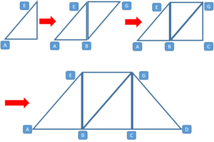
Fig. 5
This 2D wooden can be actually loaded. Place the truss on blocks of wood, use a bracket at one end that will allow the bolt connecting the two legs at A to connect as well, use two brackets at the other end that allows the truss to remain vertical but slide at D, and then connect a load to one of the bolts at B or C.
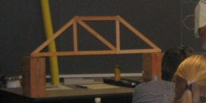
Fig. 6
